
Development of a new flood control method (PWRI type ringing)

Figure 1. The developed flood control
method (PWRI type ringing)
(Weight of material: about 200 kg,
workers required: 2, installation time:
about 20 minutes)
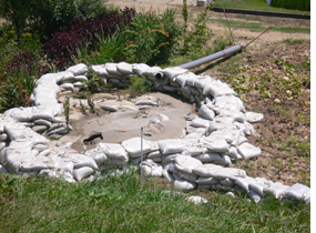
Figure 2. Example of a conventional
flood control method: ringing works
required: 25, installation
time: about 1 hour)
(Case using 150 sandbags)
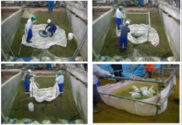
Figure 3. Test on an experimental levee
Japan’s climate includes a rainy season, typhoons, and similar meteorological phenomena. Its topography is complex with numerous steep mountains, and many of its cities are located on alluvial plains, which are flat land formed by inundation by rivers in the past. Approximately 50% of the country’s population is concentrated on such flood-disaster-prone land. Therefore, Japan has constructed river management facilities including river improvements, but flood control activities are also important for minimizing flood damage.
The Soil Mechanics and Dynamics Research Team conducts research to improve the safety of river management facilities, and also researches flood control works methods. This research includes the development of a new flood control method (PWRI type ringing) (Fig. 1).
Conventional flood control measures (Fig. 2) require large quantities of sandbags and timber, as well as many workers: typically 25 people for about 1 hour. However, the number of flood brigade members has declined as their age has risen nationwide, causing a serious shortage of personnel
This new flood control work method (PWRI type ringing) was developed to overcome these problems by establishing a leak-prevention technology that can be installed quickly by a small number of workers using few materials.
Existing flood control methods use many sandbags and large quantities of wood, whereas PWRI type ringing work or moon ring work requires only a few materials: water-blocking sheets that are strong, thin, and highly flexible, and single tubes.
A test was done using an experimental model of a river levee in a test tank at the Public Works Research Institute, and confirmed that the work can be done by two people in 20 minutes, and that it is as effective as the conventional ringing work and moon ring work (Fig. 3)
One set of materials and machinery can be loaded in a light van or similar vehicle, and when a leak is discovered by a river patrol for example, two patrol personnel can install it. Thus, the method is expected to be used as a first-response technique
This work method was patented in 2013, and has been demonstrated at flood-fighting exercises and shown at technology exhibits throughout Japan, and its us flood brigades has spread
∗Ringing method and moon ring method: Work methods executed by piling sandbags, mainly at the outlets of water leaks on berms behind levees and inside levees during floods, thereby storing water and maintaining a balance between the river and its water pressure to prevent the leakage of river water.
[Source: Understanding flood control work methods and technologies: Flood control handbook, Construction PR Association]
(Contac: Soil Mechanics and Dynamics Research Team)
Proposal for Visualizing Snowplow Movements to Assess Snow Removal Operations
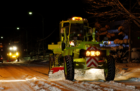
Figure 1: Snow removal operations
by snow removal graders

Figure 2: Example of visualized
snow removal operation
(click to enlarge)
Overview of the Study
In regions of heavy snowfall, which account for approximately half of Japan's area, snowfall and snow cover can seriously affect road traffic in winter. In light of this, it is essential to implement efficient and effective snow removal operations.
Road administrators divide their competent networks into some sections and implement snow removal operations for each of them. And snow removal vehicles are deployed according to the assigned length and width of each sections.
For more efficient and effective snow removal on roads, it is necessary to determine the appropriate deployment timing and organization of snow removal vehicles, as well as the routing of snow removal according to the weather conditions. Our team has been developing methods for managing snowplows in order to support appropriate decision-making. This article gives an overview of our achievements.
Analysis and Assessment by Visualization of Snowplow Movement
The Snow Removal Machinery Information Management System has been introduced by the Hokkaido Development Bureau of Japan's Ministry of Land, Infrastructure, Transport and Tourism. This system is designed to collect information on real-time location and operations of snow removal machinery. We used the data from the system to discuss and develop a method for visualizing in time series where the snow removal vehicles ran within the snow removal section.
The upper graph of Figure 2 is an example that visualizes snow removal operations.
The Vertical-axis is the Kilometer Post(KP) within the snow removal section, and the Horizontal-axis is the snow removal operation time. Colored zigzag lines show the path of each snow removal vehicle. Colored horizontal lines show major points within the snow removal section. Black diagonal lines indicate that snow removal operated at 20 km/h. Different gradients indicate different snow removal speeds, so that we can compare them with the black diagonal line to estimate the rough snow removal speed of each vehicle.
It is found from the graph that one snow plow truck and two snowplow graders were deployed on Section 1, and two snow plow trucks were deployed on Section 2. The road from KP 0.0 to KP 10.3 is four lanes, and that from KP 10.3 to KP 37.3 is two lanes.
On December 26, snow removal was conducted twice from 2:00 to 16:30, slightly changing the formation. What should be noted is that the first snow removal operation was completed at about the same time (approx. 8:00) on both sections, while the second snow removal operation on Section 2 was completed three hours later than that on Section 1. This is probably because the echelon for Section 2 had to conduct snow removal operation three times between KP 31.0 to KP 37.3, to deal with heavy snowfall. (Refer to ①.) Such a delay must be solved to secure smooth trafficability.
Visualization of snow removal operation will be useful for analyzing and assessing snow removal operations.
Future Development
By taking advantage of the visualization technique, we have been developing a system that forecasts the progress of snow removal operations based on snowfall forecasts and previously analyzed operations. The lower graph of Figure 2 diagrams the development.
In Section 1, it can be pointed out that for the second operation, Truck A did not join the echelon, Grader B and C initially began operation, and Grader C was continuing operation alone after Grader B returned to the station. The section boundary between Sections 1 and 2 is set as CP 1 (KP 17.1). If the boundary is shifted to CP2 (KP 23.4), the section between CPs 1 and 2 is expected to be operated by Truck C; thus, the operation will be completed two hours earlier.
In this way, the system under development will contribute to more efficient and effective snow removal operations on roads.
(Contact: Machinery Technology Research Team, Civil Engineering Research Institute for Cold Region)
Development of a Method That Uses FRP to Widen Highway Bridge Sidewalks

Figure 1. Widening a sidewalk
by using FRP
(click to enlarge)

Figure 2. Loading test
(in the horizontal direction on
a handrail support pillar)

Figure 3. An example of a numerical
analysis result
(deformation under load)
(click to enlarge)
1.Background
In accordance with the technical standards on road structure specified by The Road Structure Ordinance, sidewalks, as well as bicycle/pedestrian tracks, are required to be of a width sufficient to allow pedestrians, bicycles and wheelchair-users to pass in opposite directions unobstructed. Some aging road bridges have sidewalks more narrow than specified in the technical standard, because of changes in the traffic environment and so on. Accordingly, the sidewalks on such bridges must be widened to secure the safety of road users. However, the conventional widening method, in which steel sidewalks are added, makes the bridge superstructure heavier, which necessitates reinforcement of the existing girders and substructure. The resulting influence upon traffic and construction cost are issues. Additionally in the coastal areas and in snowy cold regions, roads are exposed to sea breezes and anti-freezing agents, and the resulting salt damage can cause steel members to corrode.
2.Widening the Sidewalk by Using FRP
Glass fiber reinforced plastic (FRP) has been increasingly used as a useful material for bridge structures, such as composite slabs and inspection ways. This material weighs one-quarter to one-third that of a conventional steel member and is corrosion-proof. In light of the above, we used FRP to devise a method for widening the sidewalk of a highway bridge.
In this study, we tested the material's structural performance and examined a design method through full-scale loading tests (Figure 2) and the numerical analyses (Figure 3). Our tests and analyses verified that the devised structure ensures load carrying capacity enough to support the design load, and that the structure's load resistance may be evaluated and designed by numerical analysis and theoretical calculation. The upper side of the FRP slab (i.e., the sidewalk surface) is paved to achieve skid resistance. We also verified that different paving materials adhere to FRP well and that they deform with the deformation of FRP.
Further studies will be made on appropriate structural details for various construction conditions.
(Contact: Structures Research Team, Civil Engineering Research Institute for Cold Region)