
Cleaning Seawater in a Port Using Scallop Shells
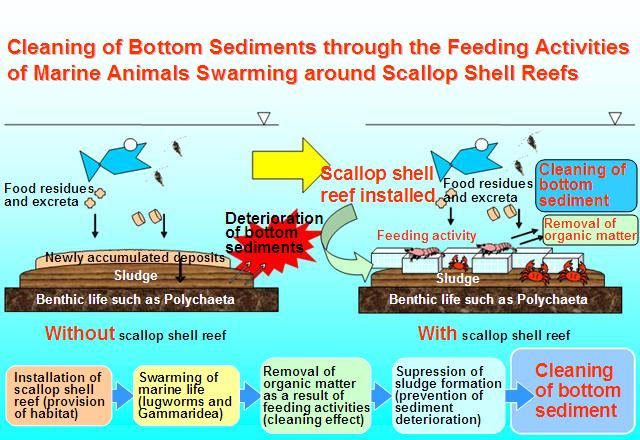 Fig. 1 Conceptual illustration of bottom sediment cleaning using scallop shell reef |
||||||
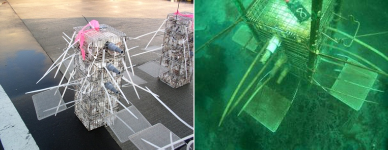 Photo 1 Experimental scallop shell reef and its installation |
||||||
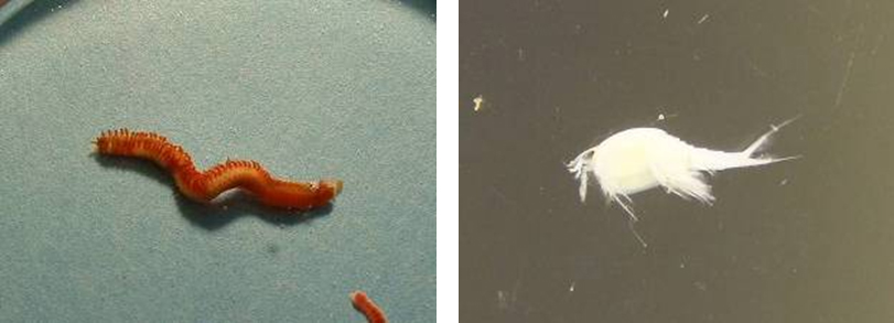
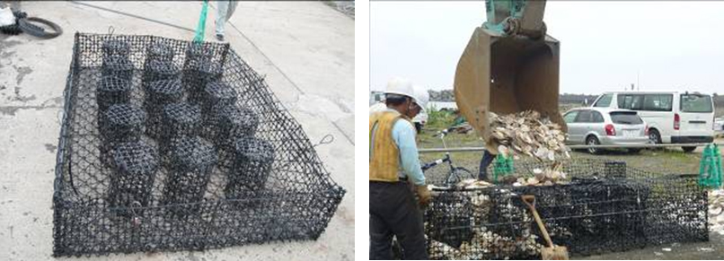
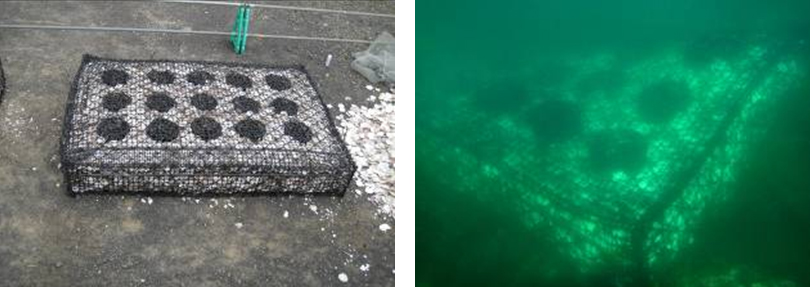
Photo 3 Production and installation of scallop shell reef for practical use |
In recent years, berths in harbors and fishing ports have been used for the stock farming of marine products. As a result, however, organic matter, such as excreta from the stocked product and fodder residues, have accumulated on the sea bottom, and deterioration of the bottom sediment has become a serious problem. Hokkaido produces about 400,000 tons of scallops every year. Half of this quantity, i.e. around 200,000 tons of scallop shells, is generated as wastes, and disposal of these wastes represents a major problem.
In order to find ways to improve the bottom sediments in ports and harbors, the Fisheries Engineering Research Team are proposing and pursuing research into scallop shell reefs, which utilize scallop shells. A scallop shell reef (afterwards referred to as a shell reef) is composed of a wire net filled with scallop shells that is placed on the seabed to improve the bottom sediments. The shell reef improves the bottom sediment through a mechanism by which the marine life living around it uses the reef as a habitat and increases to a high density; these marine creatures absorb the organic matter contained in the bottom sediment, thereby cleaning it (Fig. 1). Shell reefs may also serve as nursing grounds that allow a type of sea cucumber (Stichopus japonicus) to grow to a certain size, this sea cucumber being capable of cleaning the bottom sediment.
Experimental shell reefs, each measuring 0.2 m x 0.2 m x 0.5 m, were installed in the waters of Rakuseki Port, Nemuro City, Hokkaido, facing the Pacific, and the resulting bottom sediment cleaning effects were investigated (Photo 1). It was confirmed that various kinds of life form inhabit the experimental shell reefs, such as annelida, including a type of Spionidae (Photo 2, left), that eat deposited material, and arthropods, including Nebalia (Photo 2, right), that eat matter suspended in the water. The number of creatures inhabiting the reefs increased with the passage of time and, around 7 months after installation, reached a level capable of practical cleaning of the bottom sediment. This experiment confirmed that, using the creatures that gather within it, the experimental scale shell reefs are effective in improving the bottom sediment. It was also found that when shell reefs are placed almost touching each other, not many creatures gathered around them. This indicates the importance of there being a large surface area of contact between the reef and the seawater.
From this observation, in order to achieve a practical design, a shell reef was developed, also taking production and installation considerations into account, that has a large seawater contact area. The practical shell reef developed by the team consists of ready-made stone cages, each measuring 2.0 m x 3.0 m x 0.5 m, and internal nets inside the cages to prevent removal of the shells. To increase the area in contact with seawater, holes for the passage of water, which consist of cylinders with 0.3 m in diameter, are integrated into the cage assembly. No shells are put into these cylindrical holes. The 2 m width accommodates 3 rows of water passage holes (dividing it into 4 sections) and the 3 m length accommodates 5 rows (dividing it into 6 sections), giving a total of 15 holes, arranged at a spacing of 0.5 m (Photo 3).
A demonstration test of the practical shell reefs has just begun at Era fishing port, Matsumae Town, Hokkaido, facing the Japan Sea, where a stocking farming facility* is planned. Future activities include verification of the sediment cleaning effect of marine creatures, including Stichopus japonicus, which are expected to accumulate around the practical shell reefs, and of the effectiveness of these creatures for preserving the bottom sediment under stock farming facilities.
* Stock farming is the practice of keeping caught fish and shellfish alive in order to facilitate coordination of shipping.
(Contact:Fisheries Engineering Research Team, CERI)
Expressing Roadside Disaster Information in Maps - Roadside Landslide Hazard Maps
For Effective Implementation of Road Disaster Prevention
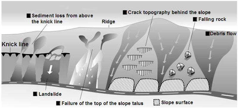 Fig. 1 The various causes of disasters concealed within slopes |
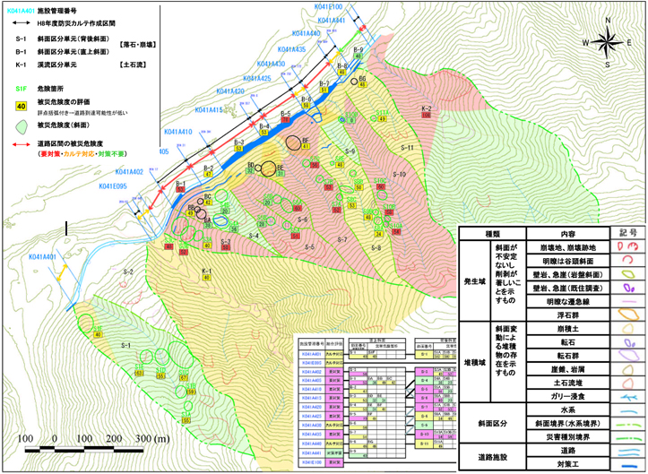 Fig. 2 Example of Roadside Landslide Hazard Map Red: Measures necessary; Green: No measures necessary |
Roads link cities and communities in various parts of Japan and serve as one of the pivotal types of social infrastructure supporting people's activities. Road networks not only cover flat areas but also extend through mountainous areas. However, in Japan, an island nation that has many steep areas, a large quantity of heavy rain and a large number of earthquakes, roads and road users often fall victim to the damage caused by natural disasters, including slope failures, rockfalls and landslides.
MLIT and Prefectural Agencies, which are responsible for the management
of Japan's roads, are actively and continuously engaged in disaster prevention
projects (such as inspection, survey, repair, improvement, and traffic
control in the event of abnormal weather conditions) in order to protect
roads and road users from the effects of natural disasters.
In order to carry out road disaster prevention projects, it is necessary to have accurate information and knowledge regarding what type of disaster is likely to occur at what kind of location, and how dangerous each disaster-prone location is. Inspections for the purpose of obtaining this information, i.e. "road disaster prevention inspections", are conducted every five to ten years. In mountain areas however, the factors that cause disasters are often hidden in slopes high up above the roads, which cannot usually be confirmed by visual checking from the roads themselves (Fig. 1). In fact, a large number of disasters have occurred that are caused by failure of or rockfalls from the upper parts of slopes lying above roads.
In response to this, the Geology Research Team has proposed a procedure to help formulate accurate disaster prevention measures that are effective against such disasters. Specifically, the proposed procedure includes the use of aerial photos, topographical data, and field surveys to search out and identify the possible causes of disasters lying hidden within slopes, and involves the incorporation of the findings and information from these activities into illustrated maps that show the distribution of danger points, possible impact on roads, status of countermeasures, and other disaster-prevention information in an easily understandable manner. The example shown in Fig. 2 expresses the danger level for each type of danger, using symbols and colors for easy understanding.
The team named this type of illustrated map a "Roadside Landslide Hazard Map" (Fig. 2) and wrote a draft manual explaining the corresponding preparation and investigation procedures. These concepts and methods have been incorporated into the procedural document "Road Disaster Prevention Inspection" for active use in disaster prevention work/projects conducted by the national government and local authorities.
(Contact: Geology Research Team)
Measuring Movement in a Landslide! (Part 2)
Observation Equipment Usable in Special Landslide Environments
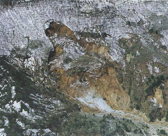 Photo 1 Fluidized landslide (Sumikawa Landslide) |
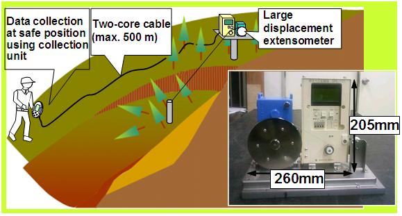 Fig. 1 Large displacement extensometer |
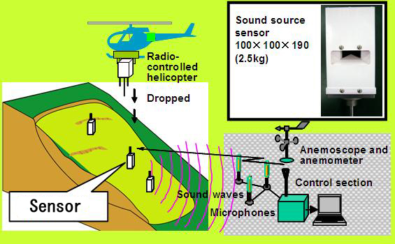 Fig. 2 Sound waves measuring system 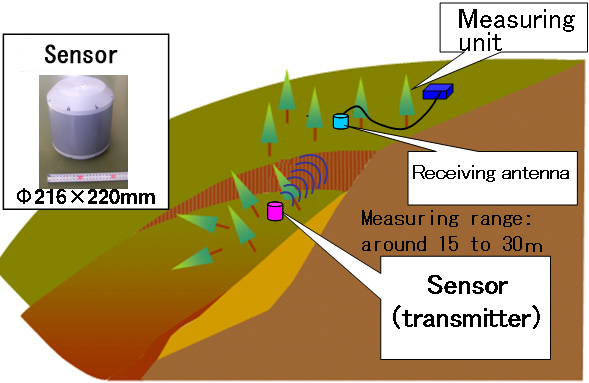 Fig. 3 Radio range measuring system |
The phenomenon in which part or the whole of a slope moves slowly downward due to the influence of groundwater and gravity is referred to as a "landslide."
At landslide sites, the evaluation of measured data recording movement of the earth mass is regarded as very important when considering warnings, evacuation and emergency measures. However, no techniques for accurate and quick measurement have been established for special landslide sites, such as landslides that cannot easily be accessed, landslides with a large amount of movement, and landslides with muddy and fluidized earth for which prediction of the ultimate range of spread is difficult.
We developed six types of observation equipment capable of performing accurate measurements in these special landslide environments.
In Part 2 of this 2-part article, we explain our equipment for measuring the movement of a landslide.
1. System for Measuring Amount of Movement of Landslide
1.1 Large displacement extensometer
To measure the amount of movement of a landmass, a wire known as an invar line is stretched across a crevice, and the extension of the wire is measured.
Conventional measurement equipment using this method has one major shortcoming,
which is that its measurement range is quickly exceeded in a landslide
that produces a large amount of movement (has a high movement speed). The
newly developed equipment includes a special spring giving tension to the
invar line, and is capable of measuring movement of up to 6 m (Fig. 1).
This equipment allows continuous measurement of landslide movement, with no gaps, at landslide sites where the movement of the slide is expected to be large.
1.2. Sound waves measuring system
When a landslide is moving in a highly active manner, it is dangerous to
enter the site, which means that it is impossible to install sensors. A
sound waves measuring system that measures large displacement was developed
as a solution to this problem.
A radio-controlled helicopter is used to position a sensor by dropping
it onto the sliding earth mass. The sensor then emits sound waves, which
are received by microphones positioned outside the landslide area. The
distance to the sensor is measured using the arrival time of the sound
waves (Fig. 2).
This measuring system allows measurement of a landslide with large mass movement for which access is difficult.
1.3 Radio range measuring system
One of the problems with conventional measuring equipment is its inability to perform measurements when buried in the landslide mass. The radio range measuring system was developed as a solution to this problem. Low frequency radio waves (around 1 kHz), which are largely unaffected by coverage with soil or water, are used to measure the distance from the sensor to the receiving antenna (Fig. 3).
This measuring system allows continuous measurement of the movement (distance
traveled) of the landslide, even though the sensor is buried in the sliding
mass.
(Contact: Landslide Research Team)