
Field experiment on technology of sediment discharge from a dam reservoir using water level difference
When a dam is built on a river, sand that is carried by water in the river accumulates in the reservoir. This causes the following problems.
·Reduction in the effective capacity of the dam (Most reservoirs in Japan have secured capacity for sediment to accumulate for 100 years, but sediment accumulation progresses faster than the estimated speed in some reservoirs)
·Changes in the riverbed environment at the lower reaches of a river (reduction of small-diameter sediment in the riverbed, riverbed material is not renewed, etc.)
·Reduction of sands at downstream beaches
Therefore, technology to discharge sediment from a reservoir and supply it to a downstream part of the river is required to extend the life of the reservoir and improve the riverbed environment of the lower reaches of the river.
Based on the background given above, the River and Dam Hydraulic Engineering Research Team researches and develops technologies for discharging sediment that are economical and applicable to many reservoirs. Based on results from experiments using models, we propose the technology of an “burrowing-type sediment removal suction pipe.” The pipe is a U-shaped flexible pipe with one end used as the intake, holes made on the curved part and bottom of the upstream part of the pipe used as openings for suction of sand, and a device for sucking sand like a vacuum cleaner using the energy of water that flows from the higher part of the reservoir to the lower part. To confirm the functions and grasping the problems of this technology for actual use in the future, a field experiment was conducted at an actual small reservoir.
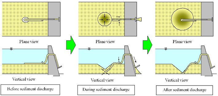
Image of the burrowing-type sediment removal suction pipe
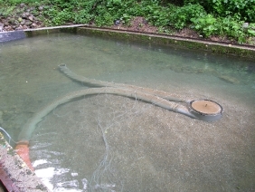
Situation before sediment discharge
(shot from downstream side
on the right bank)
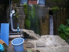
Situation of downstream side of
the dam during sediment discharge
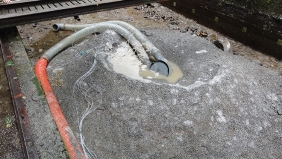
Situation after sediment discharge
(shot from downstream side
on the right bank)
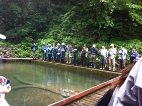
Scene from the inspection tour

Location of the Takayama City
(click to enlarge)
This field experiment was implemented at a facility named the Hiru-dani experimental dam in Takayama City, Gifu Prefecture, in Jul. 2012. The Hiru-dani experimental dam is a facility of the Hodaka Sedimentation Observatory, Research Center for Fluvial and Coastal Disasters, Disaster Prevention Research Institute, Kyoto University. It is located in the Ashiaraidani watershed upstream of the Gamata river in the Jinzu river system; it is a small dam for observation of the flow rate and the sand and gravel discharges (length: 14m, width: 6.55m, height: 4.65m).
In the experiment, a sediment discharging pipe with a pipe diameter of 20cm was used; sand was discharged using a water level difference of about 3m from the dam to the lower reaches of the river. In the results, 3.45m³ of sand was discharged in 52 min at a flow rate of 0.113m³⁄s. The depth of scoured sand at that time was about 1m, and the concentration of sand was 3%–6% initially. Information that will serve as a useful reference for practical implementation was acquired. No major problems were encountered in the installation and removal of the sediment discharging pipe, which were done relatively easily. However, for practical implementation, information on pipes with larger diameters and countermeasures against garbage such as driftwood in actual reservoirs, etc., must be considered.
The Okuhida sand control and civil engineer training session was held in Jul. 2012 at the Hodaka Sedimentation Observatory mentioned above; this was hosted by the NPO Research Center of Nature and Culture of Mountains. As part of this training session, there was a occasion to explain sediment control technology to about 90 participants from universities, private companies, sabo engineers, etc., and provide an inspection tour of a field experiment. During the question-and-answer session in the tour, there was active discussion about the mechanism of sediment discharging technology and applicability to actual sites, etc. We would like to consider more details of the discussion in the future research.
(Contact: River and Dam Hydraulic Engineering Research Team)
Concrete-channel Frost Damage Diagnosis Using the Ultrasonic Pulse Method
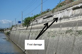
Photo 1 Frost damage
on a concrete open channel

Fig.1 Conceptual diagram of the
surface scanning method
Extract from “Concrete Non-destructive
Testing Techniques” by Chuji Kashiwa
(click to enlarge)

Fig.2 Results of measurement using
the surface scanning method
(with no internal cracks)
(click to enlarge)

Fig.3 Results of measurement using
the surface scanning method
(with internal cracks)
(click to enlarge)

Photo 2 Appearance of a sample core
Figures 2 and 3 and Photo 2 are extracts
from the Journal of the Japanese Society
of Irrigation, Drainage and
Rural Engineering (Suido no Chi) 80 (6)
(click to enlarge)
A large number of irrigation and drainage channels support food production in Hokkaido, with the total length of irrigation channels constructed under national projects alone amounting to several thousand kilometers. More than half of all such facilities have reached or will soon reach the end of their projected service life. Against this background, channels are now checked on a regular basis to detect the risk of side-wall collapse and damage to channel side walls/bottoms in order to secure regional water supply. Based on the results, channels are repaired or reconstructed.
Photo 1 shows a sidewall of a concrete open channel. In Hokkaido and other cold regions, concrete may be subjected to frost damage. Water in the material expands upon freezing, and frost damage causes concrete deterioration through repeated freeze-thaw action. In Photo 1, horizontal hairline cracks are seen in the upper part of the wall. It is important to understand the extent of frost damage through inspection of irrigation channels in cold regions.
As frost damage affects the inside of concrete as well as the surface, it is impossible to fully grasp its extent from appearance alone. To assess the need for repair and reconstruction, a simple diagnosis technique for determining the extent of damage inside channel concrete is required.
The Irrigation and Drainage Facilities Research Team is involved in study work based on the potential for the use of ultrasound in such diagnosis. The surface scanning method shown in Fig. 1 is an example of ultrasound application. In this system, a transmitter and a receiver serve as the start and the goal of moving ultrasound waves. The distance between the transmitter and the receiver is gradually increased, and the time taken for ultrasound to reach the receiver is measured. Results are shown in the graph at the bottom of Fig. 1, where the abscissa and the ordinate represent distance and time, respectively. Concrete deterioration from the surface down to a certain depth can be shown in the form of a graph with a sloping line that becomes gentler in the middle (the dotted line (a) in the figure). The depth of deterioration from the surface can be calculated using this graph.
Inspection results for actual channels are shown in Figs. 2 and 3. The line in Fig. 2 is similar to the dotted line (a) in Fig. 1, by which the deterioration depth from the surface can be found. Fig. 3, in contrast, shows examples in which the graph slope becomes steep in the middle and the two lines do not intersect. Examination of a column sample collected from the concrete sidewall whose results are shown in Fig. 3 showed cracks inside the structure.
Based on this method’s significant potential to support the detection of internal cracking in sidewall concrete as well as surface deterioration, CERI remains committed to its efforts to confirming the validity of the approach.
(Contact: Irrigation and Drainage Facilities Research Team, CERI)