
Safety Evaluation of Treated Sewage Using Aquatic Organisms (Bio Assay)

Photo 1 Water-flow type medaka
exposure system (click to enlarge)

Photo 2 Observing fertilized eggs
of medaka (click to enlarge)

Photo 3 Algae growth inhibition test
with micro plates (click to enlarge)
Sewers collect wastewater containing various substances from factories, workplaces and homes. The collected wastewater was treated in a sewage treatment plant. The number of kinds of chemical substances contained in pharmaceutical and personal care products has been on the rise in recent years. Because a part of them are released into rivers, their negative influence on aquatic organisms is a concern.
The PWRI Water Quality Research Team has evaluated the influence based on production of a protein called vitellogenin (yolk precursor) that is used as an indicator of feminization of male fish for fish species, and swimming inhibition of daphnia for crustaceans. However, it is important to evaluate the influence on reproduction in order to maintain a sound ecosystem. For this purpose, PWRI has improved laboratory equipment and built an experiment framework for "spawning tests" using medaka, "short-term chronic toxicity tests" to check the hatching rate of fertilized eggs and the survival of juvenile medaka and zebra fish, as well as " daphnia reproduction tests" for crustaceans and "growth inhibition tests" for algae.
For fish spawning tests, a system using flowing water has been built at the laboratory in Kasumigaura wastewater treatment plants, Ibaraki Prefecture, which enabled collection of test data using actual sewage samples (Photo 1). For short-term chronic toxicity tests, it is now possible to bring sewage samples to PWRI for testing in the laboratory (Photo 2). For algae growth inhibition tests, test efficiency has been improved with using micro plates to enable testing of many samples at one time (Photo 3)
Through these experiments, Water Quality Research Team is studying impacts of treated sewage on aquatic organisms. If impacts on aquatic organisms are found, the team will develop technologies to reduce them.
(Contact: Water Quality Research Team)
Building Embankments Strong against Earthquakes

Table Number of major
earthquakes in the past 20 years
(click to enlarge)
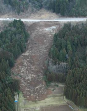
Photo-1 Example of damage
to embankment

Photo-2 A model test
(Above: without measure;
below: drained) (click to enlarge)
Earthquake country Japan
The Tohoku-Pacific Ocean Earthquake (Great East Japan Earthquake)
that occurred on Mar. 11th, 2011, is still fresh in our minds. Though we
say "a natural disaster strikes when people lose their memory of the
previous one," a major earthquake occurs somewhere in Japan almost
every year. The table shows the number of earthquakes with a seismic intensity
of a lower 5 or greater in each year for 20 years from 1993 to 2012. Though
they include the aftershocks of the Great East Japan Earthquake, there
have been 244 earthquakes with a seismic intensity of a lower 5 or greater
in these 20 years. Among them, there are as many as 42 earthquakes with
a seismic intensity of a lower 6 or greater. As you can see representative
earthquakes named in the remarks columns of the table, the areas hit by
the earthquakes are distributed from Hokkaido to Kyushu.
Damage to embankments caused by earthquakes
These earthquakes caused damage to various facilities. House collapses and landslides are representative examples but earth structures ("embankment") including road embankments and river levees also suffer a great deal of damage (Photo 1 is an example of damage to a road embankment). It is obvious at a glance that water is involved in damage caused by heavy rain from typhoons, etc. Water in embankments and ground also greatly influences earthquake damage. As you may know from news reports, liquefaction of ground or embankments is one example (liquefaction was described in WEB Magazine vol.23).
In order to build embankments strong against earthquakes
In order to build earthquake-resistant embankments, it is necessary to think about how to handle water. Photo-2 is an experiment to compare the damage of an earthquake by changing the water level in the embankment. The embankment collapses when the water level is high but it does not collapse when the water level is lowered by draining. This way, just adequately draining water in the embankment can make it stronger against earthquakes. When building a new embankment, you can devise ways to prevent water from entering the embankment, drain water in it and build a strong structure beforehand. For an existing embankment, on the other hand, you need to consider ways other than those for new embankments because it is difficult to break an existing embankment and build a new one. The Soil Mechanics and Dynamics Research Team first carries out investigation of the parts of levees and road embankments damaged by an earthquake for traces of possible impacts of water, groundwater conditions, topography, physical properties of the soil used for the embankment and foundation ground, etc. to grasp the collapse mechanism when they were hit by the disaster. Then, in light of the findings of the local investigation, the team creates models reproducing the ground and embankment conditions and studies effective measures for new and existing embankments by experimenting and analyzing methods to drain water from soil, harden earth using fixation agents, reinforce embankments with sheets of reinforcing material and other methods.
(Contact: Soil Mechanics and Dynamics Research Team)
Development of a Repair and Reinforcement Method for Reinforced Concrete
Slabs in Cold, Snowy Regions:
A Study toward Extending the Lifespan of Highway Bridges


(a) (b)
Deteriorated Collapsed
part
upper surface
Fig. 1 Damage to a highway bridge
deck slab (click to enlarge)
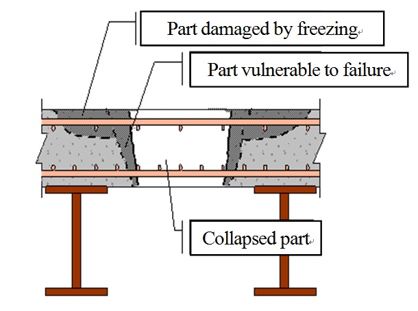
(a)Diagram of damaged area
(cross section)

(b)Diagram of repaired area
(cross section)
Fig. 2 Deck slab repair method
(click to enlarge)
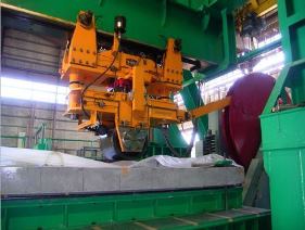
Fig. 3 Wheel running test
Highway bridges in cold, snowy regions have recently been found to have unexpectedly severe damage to their RC slabs - the bridges' main structural elements - caused by freeze-thaw damage in combination with salt damage, and exacerbated by repeated loading from passing vehicles. As shown in Figure 1, deterioration in the upper side of highway bridge concrete slabs has caused cracks in the asphalt pavement and, in severe cases, further degradation has lead to partial collapse of the slab. This issue has become a major one in road management. Not only does such deterioration affect the safety of vehicles on the bridge, but it may also affect third parties on over-bridges.
It is known that the presence of water on the upper side of a deck slab great influences such deterioration. To eliminate this influence, newly built RC slabs are waterproofed over their entire surface. However, the current specifications for deck slab waterproofing lack sufficient consideration for the conditions in snowy, cold regions. Also, the RC deck slabs on a great number of existing bridges do not have waterproofing over their entire surface. In light of the above, more cases of damage to RC deck slabs are expected. Given these circumstances, and considering budget constraints, the large-scale repair of existing slabs promises to be difficult, and efficient and effective measures for partial repair are required.
The present study aims to develop a partial repair method for RC deck slabs in response to snowy, cold environmental conditions, toward extending the lifespan of existing bridges. More precisely, as shown in Figure 2, the improvement of durability is pursued by ensuring appropriate waterproofing, as well as by repairing the collapsed portions of slabs and deteriorated portions of the upper side. In this study, the process of deterioration and damage was analyzed by examining deterioration and damage to RC slabs of existing bridges, and using field-scale samples that were subjected to simulated damage, wheel running tests (Figure 3) and other tests were conducted to examine methods of treating the surface of the repaired portion and to examine the load bearing ability and durability of various repair materials.
(Contact: Structures Research Team, CERI)