
The battle with earth - A history of retaining walls -

According to statistics, mountainous areas account for 60% of Japan's territory. Only 12% of Japanese territory is flat land with slopes of less than 3 digrees.
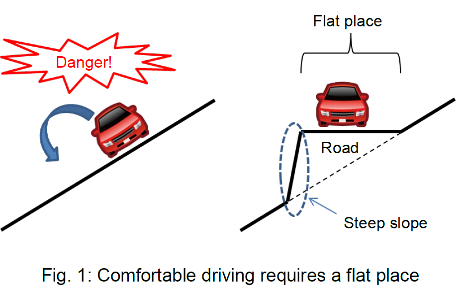
At any rate, people need flat places in order to live comfortably. Hence, the technology for production of flat land is very important. The same also applies to basic facilities within society, such as roads.
A steep sloping surface will always be necessary when attempting to turn a slope into a flat place. Earth is a loose collection of fine particles, and to a certain degree of sloping the earth particles do not collapse because they are meshed together, but collapse is inevitable once a slope exceeds a certain angle.
Therefore, retaining walls are structures that are built in order to support earth that seems likely to collapse.
"Retaining wall" is called "Yo-Heki" in Japanese. "Heki" means wall and "Yo" means to hold or support.Eearth is held or supported by retaining walls.
The force that triggers earth collapse is known as "earth pressure". Earth pressure exerts a force that pushes against the retaining wall horizontally. Retaining walls must resist this earth pressure.
There are various types of retaining wall. It can be said that the history of retaining walls is the history of a battle with earth.
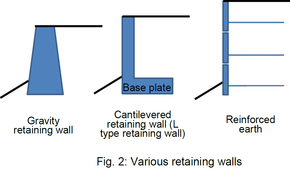
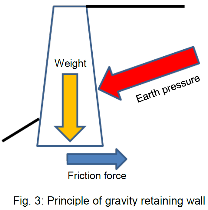
The most basic retaining wall is the gravity retaining wall. The gravity retaining wall resist earth pressure with friction force caused by its weight.
On steeper slopes, or when attempting to produce more spacious flat places, the height of the retaining walls becomes steadily larger. With a high gravity retaining wall, the necessary weight also becomes steadily greater. Eventually, the ground surface (foundation ground) behind the gravity retaining wall becomes unable to sustain its weight.
Therefore, gravity retaining walls are mostly used up to a height of around 5m.
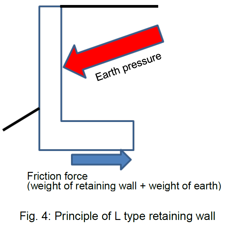
When there is a need for a retaining wall that is higher than a gravity retaining wall, a "cantilevered retaining wall" is used. These retaining walls are described as "inverted T type" or "L type" retaining walls according to their appearance.
A characteristic of the cantilevered retaining wall is that it has a plate known as a "base plate" that runs behind the wall. Earth pressure is a force exerted by the weight of earth that could collapse. By taking this weight of earth, the base plate of the cantilevered retaining wall also uses the weight of earth in resisting horizontal sliding.
With a cantilevered retaining wall, when thinking of earth as luggage that a person is attempting to move by pushing, it is as though earth is pushed in a state where one has trodden on the edge of the luggage (= retaining wall) that one is attempting to push. In this case, it will not be possible to push the luggage along as planned. The cantilevered retaining wall is able to push earth simply by giving a pointless task to the earth.
Cantilevered retaining walls are mostly used as retaining walls of a height that exceeds 10m. If the retaining wall becomes higher still, the pushing force of the wall will steadily become stronger. Eventually, the wall will break. Alternatively, the wall will become steadily thicker and heavier, causing the base ground to collapse.
As level ground is progressively developed and cities are formed, roads gradually tend to be diverted into steep mountains. When this happens, the slopes on construction sites become ever steeper, and retaining walls are also required to become higher still.
Around 50 years ago, a type of retaining wall was developed with a completely new concept: the "reinforced earth wall".
The first person in the world to conceive of reinforced earth wall was a Frenchman called H. Vidal. He is said to have come up with the idea for this method when noticing that a pine leaf inserted into a sand dune would cause the sand dune to increase in height.
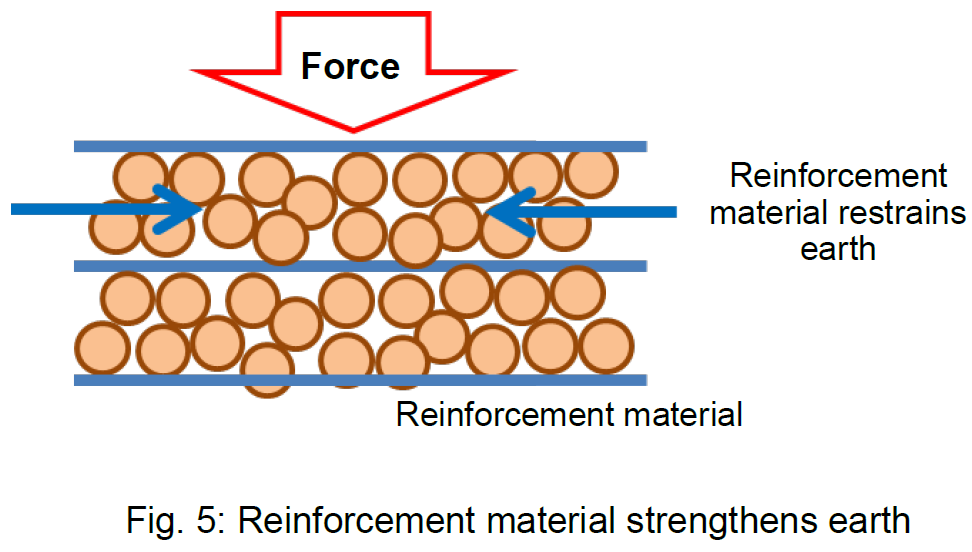
Reinforced earth possesses a mechanism whereby reinforcement materials are placed inside earth, binding earth particles together, and thus restraining particles of earth that are likely to collapse. Retaining wall up until now were based on the principle of to what extent they could limit the earth pressure that would cause earth to collapse, but reinforced earth is based on precisely the exact concept of not letting earth collapse.
From long ago, it was widely thought that mixing earth with other materials would make it less likely to collapse. For example, the "Mizuki" that was built as a protective wall in Kyushu in the 7th century had branches of trees, etc. spread out beneath its embankment so as to prevent earth (and the embankment itself) from collapsing. The walls of Matsumoto Castle, which was constructed in 1504, featured rope woven in-between clay in order to prevent the walls from collapsing.
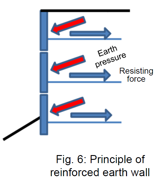
Fig. 6 shows the resistance mechanism of reinforced earth. Reinforced earth is inserted with reinforcement materials at fixed intervals. Reinforcement materials are connected to the wall that is placed in front of the retaining wall. Earth pushes the wall frontward as earth pressure, and at the same time the reinforcement materials are pressed down under weight, stopping the wall from moving forward.
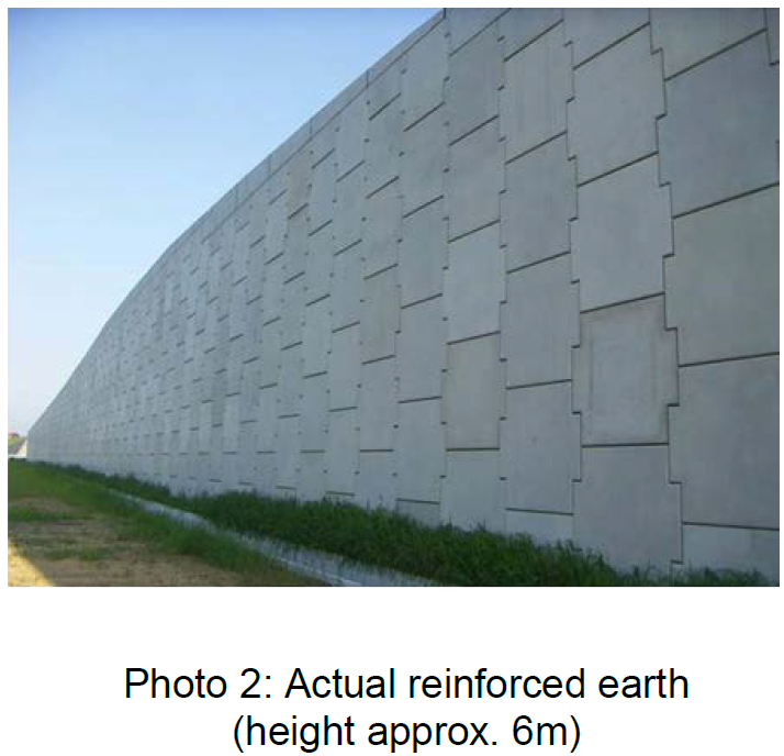
Additionally, if we are going into such detail, although similar to the principle of cantilevered retaining walls, another characteristic is that while a cantilevered retaining wall pushed down earth brought together under the lowest retaining wall, reinforced earth wall pushes down earth finely at each level starting from the top. With a cantilevered retaining wall pushing down earth together, there is an extremely large force applied to the base of the vertical wall, and the wall becomes thick; with reinforced earth wall, however, a high retaining wall can be produced with an extremely thin wall. Reinforced earth is also often seen where heights exceed 10m.
At the outset of this article, we stated that "the history of retaining walls is the history of a battle with earth". Around the 5th century BC, Chinese military strategist Sun Tzu outlined "The Art of War" in a famous military text of the same name, compiling methods of attaining victory in battles, and this text can be found on sale bookshops where it is bought for application in achieving success in business.
"The Art of War" describes various things that are important for achieving victory in battle, including the act of making the enemy engage in futile exercises, personally avoiding futile pursuits, and dividing the enemy into many parts and not permitting the enemy to gather itself together.
Comparing retaining wall technology to Sun Tsu's "Art of War", it could be said that the cantilevered retaining wall is a technology that defeats the enemy (earth) by making it engage in futile exercises and thus causing it to become weak, while reinforced earth wall is a technology that defeats the enemy (earth) by refusing to permit it to gather itself together and making it scatter, in which case Sun Tsu's "Art of War" can even be applied to civil engineering technologies.
(Contact: Construction Technology Research Team)
Technology for examining the inside of concrete by using high-output X-ray
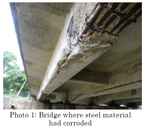
Since concrete is resilient against compression but weak when stretched, concrete structures such as bridges are strengthened with steel materials such as reinforcing bars and cables. Concrete is an alkaline material and normally protects steel material, but when water containing salt content permeates into the concrete, the steel corrodes, causing expansion, and cracks appear in the surface of the concrete. If this progresses further still, concrete will come unstuck on the outside as seen in Photo 1, causing the steel material to be cut off and thus rendering the bridge unusable.
In order to perform appropriate maintenance and management, it is important to quickly detect any deterioration (such as corrosion of internal steel materials) and take countermeasures. However, it is very difficult to ascertain from the outside the state of steel materials within concrete. Therefore, just as humans take X-ray scans, a technique is being developed in order to use X-rays for examination of steel materials within concrete.
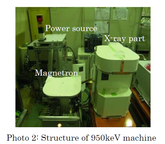
Up until now, the output of X-ray equipment that can be carried outside was around 300keV, but it is difficult to examine the inside of thick concrete with this level of output. Together with The University of Tokyo, the PWRI has developed X-ray equipment having high output levels of 950keV and 3950keV, and this is being used to photograph actual bridges. As shown in Photo 2, the developed 950keV machine is divided into an X-ray part, a magnetron and a power source, each of which weighs about 50kg and can be carried to sites in order to perform examinations.
In one bridge, corrosion and fracturing of steel material was seen when peeling out concrete to view the steel material in order to carry out repairs on the concrete. This bridge was examined with the 950keV X-ray equipment.
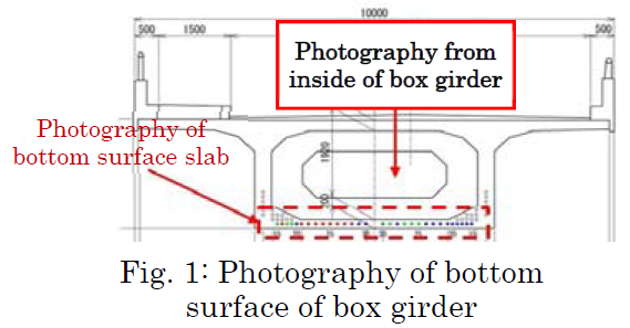
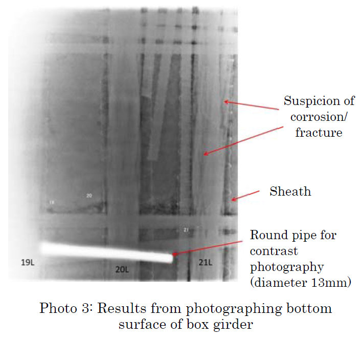
The machinery was brought in from a manhole for inspection inside a box girder, and the bottom surface of the girder was photographed. By moving the X-ray source inside the box girder and the detector outside the box girder to take photographs, a wide across the bottom surface of floor slabs can be photographed. As shown in Photo 3, it was possible to detect sites of corrosion and fracture in the sheath (casing pipe) used to pass the steel material and in the steel material therein.
It has thus become possible to use high-output X-ray to examine the corrosion and fracture, etc. of steel material inside concrete bridges, which is impossible to discern through visual checks alone. We hope to deliver early detection and early treatment by combining this method with other non-destructive test methods.
(Contact:CAESAR)