
Confirmation of long-term drainage effects and durability in peaty farmland
- Verification of the effects of a culvert in peaty farmland, using scallop
shells as a filter -
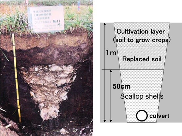 Cross section of a scallop shell culvert |
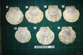 Scallop shell filter material 11 years after construction |
A type of soil known as peaty soil is distributed extensively throughout Hokkaido. Peaty soil in cold regions is formed by gradual accumulation of dead hygrophytes in wetlands, which do not decompose due to low temperatures. Since the areas with this type of soil were originally wetlands, the groundwater level is high and needs to be reduced, by draining excess water, for use as farmland.
To lower the groundwater level of farmland, a drainage system known as a culvert is constructed. In the past, this work was usually conducted by excavating soil linearly to a depth of around 1 m, installing underground drainage pipes and then returning the excavated soil. However, since poor drainage occurs shortly after applying this method, a method of using culverts with filter material has recently become mainstream. In this method, filter material with good drainage properties is used instead of returning the excavated soil, and this is then covered with surface soil.
However, since this method has spread only recently, the durability of the filter material was unclear and it was necessary to clarify this for rational renewal of culverts.
Accordingly, CERI has been conducting routine research at the same place to determine the service life of culverts using scallop shells as the filter material. These shells are produced in large amounts in areas with many scallop farms in northern Hokkaido and the Sea of Okhotsk coast. The results confirmed that the drainage was sufficient and that scallop shells remained intact without dissolving or breaking due to the highly acidic water peculiar to peaty soil, even 11 years after the construction. We are planning to continue the research at the same place in the future to determine the service life of scallop shells as a filter material for culverts, and develop technical guidelines for rational renewal of such culverts.
(Contact: Rural Resource Conservation Research Team, CERI)
Constructing safe dams by clarifying mechanisms for seepage failure by water flow in soil
- Developing a large-scale laboratory seepage failure test machine capable of conducting tests under various conditions, and research on seepage failure mechanisms -
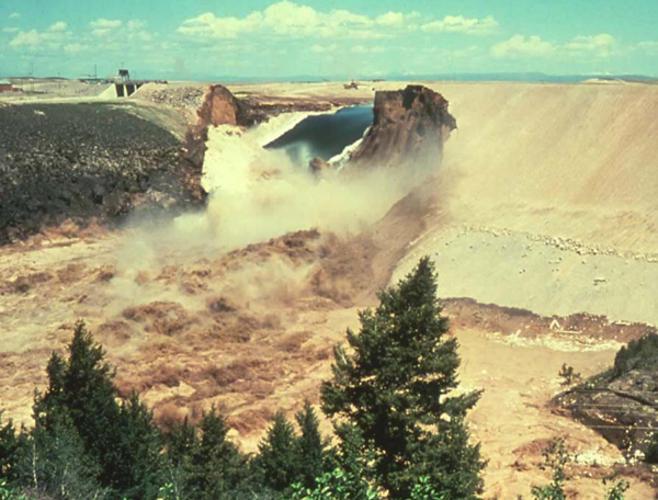 Failure of the Teton Dam |
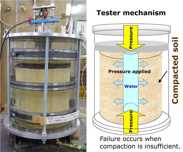 The developed large-scale laboratory seepage failure test machine capable of testing under various conditions |
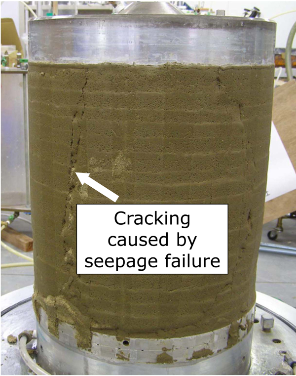 Soil in which seepage failure occurred in laboratory testing |
Dams and levees are built to protect lives and property from floods. A levee is basically constructed with soil. And among the various types of dams, a type known as a "fill dam" is also made of soil. Because a fill dam stores water, it constantly has water flowing through it. Likewise, water flows through a levee whenever a flood occurs. Water flowing through a fill dam or levee (called “seepage”) can sometimes lead to failure of the dam or levee. This phenomenon is called "seepage failure."
Seepage failure gained international recognition in 1976 when the Teton
Dam in the United States failed. The Teton Dam’s failure is thought to
have been primarily caused by inadequate foundation treatment of the dam’s
foundation rock. Since then, many researchers and engineers have conducted
research on seepage failure caused by water flowing through soil and bedrock.
However, because such flow cannot be directly observed, the mechanisms
that cause seepage failure as well as the conditions under which it occurs
are not adequately understood.
Building dams and levees that are safe from seepage failure requires that the mechanisms and causal conditions of this phenomenon be fully understood. However, using an actual dam or levee to conduct seepage failure experiments would result in its destruction and is therefore problematic. Consequently, seepage failure must be studied through laboratory tests that appropriately recreate actual dam and levee conditions. To address this need, we developed a large-scale laboratory seepage failure test machine that is capable of conducting tests under various conditions. We are currently using this device to conduct research on the mechanisms of seepage failure and the conditions under which it occurs.
In the tests we have conducted thus far, we have found that, if soil is
sufficiently compacted based on current fill dam construction standards,
no seepage failure will occur when the speed of change in the dam’s water
level is normal. Conversely, tests in which soil compaction did not meet
current fill dam construction standards revealed that seepage failure will
occur. These findings point to the importance of full soil compaction in
dam and levee construction to prevent seepage failure. Of course, results
are dependent upon use of appropriate soil, thorough foundation treatment
of the dam’s foundation rock, and other factors. We will continue pursuing
our research by conducting tests under a variety of conditions.
(Contact: Dam Structures Research Team)
An approach to quality evaluation of concrete structures
- Quick testing of permeability using electrophoresis -
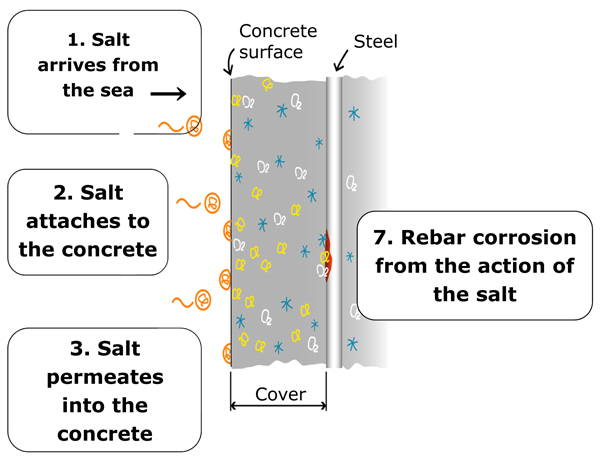 Figure 1: Attached salt permeates into concrete |
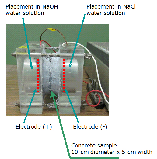 Figure 2: Test of salt permeability using electrophoresis |
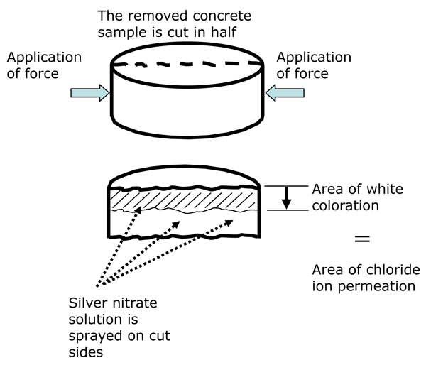 Figure 3: Method for checking test results |
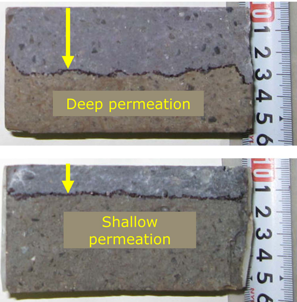 Figure 4: Test result: The lower concrete is more resistant to salt penetration |
Bridges, tunnels, retaining walls, and other concrete structures are dependable
forms of social infrastructure that support our daily lives. We tend to
think of these structures as being permanent, something we can use forever.
However, in some cases, they can deteriorate and require repair or reinforcement.
As is shown in the diagram of Figure 1, salt can penetrate into concrete
from its surface and cause "salt damage" whereby rebar within
the concrete corrodes. Salt damage requires caution because it can lead
to major structural damage. This makes it desirable to use concrete that
resists salt penetration as much as possible. Moreover, if the salt permeability
of concrete can be quickly measured, this information can be used as a
rough standard in evaluating concrete quality.
The need to develop a testing method
So, how can the salt permeability of concrete be measured? Although at first glance concrete appears to be a substance through which nothing can pass, it actually contains extremely small openings that are invisible to the naked eye. Little by little, chloride ion penetrates into the concrete through these openings. It is possible to test chlorine ion permeation in concrete by simply immersing the concrete in a saline solution. However, obtaining results from such a simple method can take over a year. This makes it necessary to devise a testing method that can obtain results more quickly. Responding to this need, PWRI’s Concrete & Metallic Materials Research Team began to develop a method that uses electrophoresis.
Principle behind testing
The principle behind the test is as shown in Figure 2. A water solution
of sodium chloride and sodium hydroxide is poured in on both sides of a
cylindrical concrete sample. Then electrodes are installed and a fixed
voltage of direct current is provided. Chloride ions, which are anions,
move through the concrete toward the positive electrode with the force
of electricity (electrophoresis). After electric current has passed for
a certain amount of time, the sample is removed and cut in half as shown
in Figure 3. The cut sides of the halves are then sprayed uniformly with
a silver nitrate solution. When sprayed, areas into which chlorine ions
have penetrated will turn white due to a reaction between silver ions and
chloride ions. As is shown in Figure 4, the depth of permeation varies
in accordance with the concrete’s quality. The Concrete & Metallic
Materials Research Team is currently accumulating further test data with
the aim of making this new test method practically applicable.
(Contact: Concrete & Metallic Materials Research Team)
Promotion of a Resource-Recycling-Type Revegetation Method
- Let’s create greenery using unprocessed surplus soil -
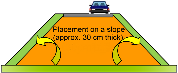 Fig. 1 Utilization of surplus soil |
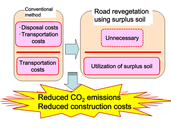 Fig. 2 Effects of utilization of surplus soil |
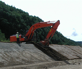 Photo 1 Placement of surplus soil |
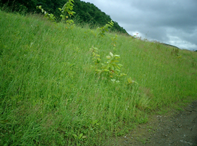 Photo 2 Condition of restored greenery after construction (10 months later) |
What is surplus soil?
Surplus soil is surface soil removed together with the weeds on it. While
it was sometimes mixed with soil and used at the bottom of embankments,
in general it was discarded at disposal sites without being used.
Advantages of using surplus soil
Since embankments are made of soil they weaken when they absorb rainwater.
Grass is usually planted on embankment slopes to protect them from rain.
Since surplus soil contains seeds and roots in large amounts, slopes can
be covered with vegetation by replacing the unprocessed surplus soil. This
eliminates the costs incurred in transporting and disposing of surplus
soil and the purchase of revegetation materials, making it possible to
reduce both CO2 emissions and construction costs. Effective use of surplus soil as a resource
is a resource-recycling-type revegetation method using native species,
since seeds and roots contained in surplus soil are from plants originally
growing at the place. It can also reduce the impact of construction work
on the ecosystem.
Therefore, tests of the technique of using surplus soil as revegetation material were conducted on road slopes in different areas of Hokkaido, and the growth conditions were observed to examine the revegetation effect. The results revealed that surplus soil can be used as revegetation material, enabling significant cost reduction regardless of the embankment soil properties, types of surplus soil or period of construction. Revegetation using surplus soil was adopted as a standard method of the Hokkaido Regional Development Bureau, Ministry of Land, Infrastructure, Transport and Tourism, from FY 2008.
Further utilization of surplus soil
While surplus soil was found to be effective as a revegetation resource,
the area to which it can be applied effectively is limited as the amount
generated by one construction project. Since it is considered possible
to increase the area by reducing the thickness of surplus soil placed on
road slopes, tests and surveys are currently being conducted by reducing
the thickness from the standard 30 cm. Although the results may vary according
site conditions, it seems to be effective even if the thickness is reduced
to around 10 cm.
We are planning to verify the growth conditions and durability through further data collection and analysis, and present more efficient revegetation methods using surplus soil in the future. In addition, since plant growth conditions are very good (sometimes too good) when surplus soil is used, means to reduce maintenance and management work by controlling growth will also be considered.
(Contact: Geotechnical Team, CERI)