
Development of bridge inspection technology
Development of technology for ultrasonic inspection of cracks emerging
in steel bridges
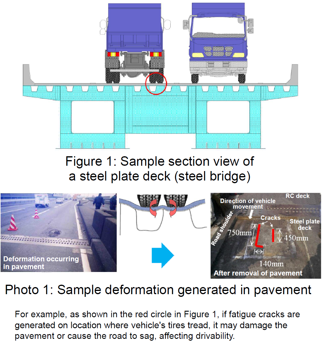
Note: Figure 1 and Photo 1 show different samples. The type of structure is different.
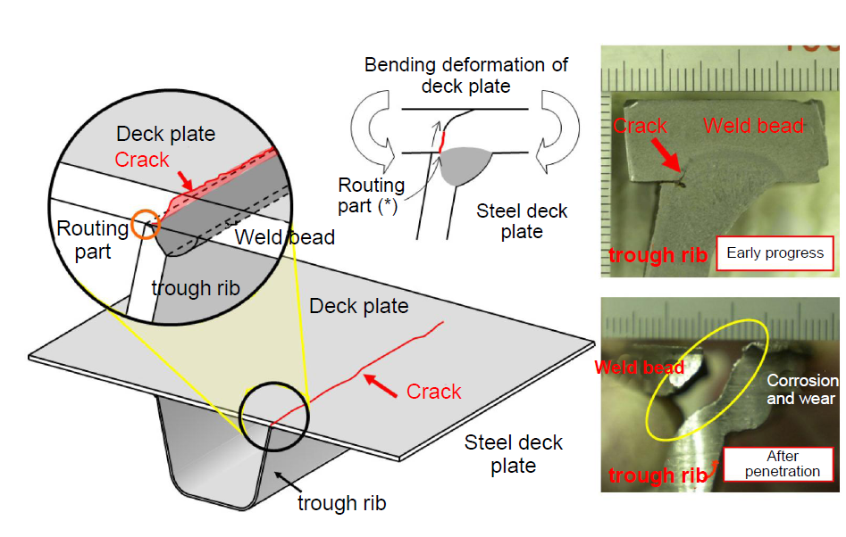
Figure 2: Sample metal fatigue cracks
generated in a steel deck plate
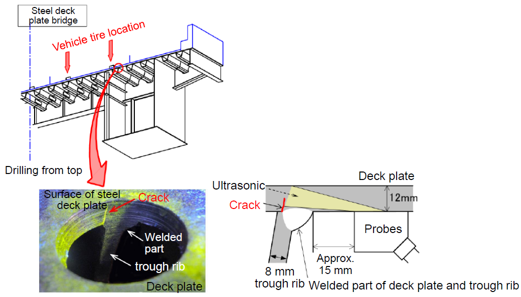
Figure 3: Image of the developed ultrasonic
flaw detection technology
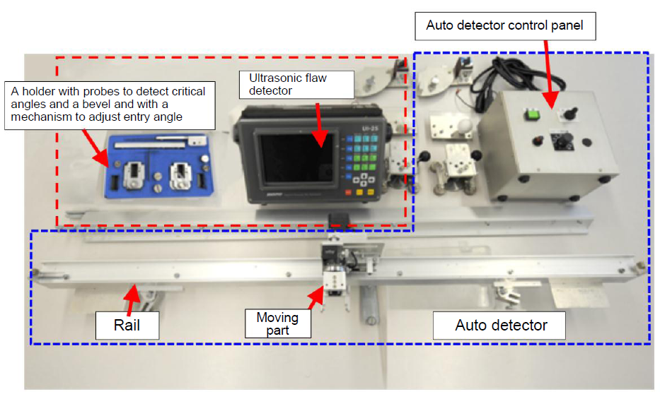
Photo 2: A view of the developed
ultrasonic flaw auto detector
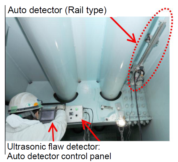
Photo 3: Sample test used for actual bridge
Bridges are mainly categorized by their construction materials into steel
bridges and concrete bridges. Although both steel and concrete are very
strong and sturdy, bridges will eventually get damaged with long-term use.
Among the various types of bridges, those made from steel (called steel
bridges) get particular kinds of damage: rust and fatigue. Coating is effective
to prevent rust. Even if the coating is damaged, recoating can prevent
rust. Let us explain the other damage, fatigue, here. Continuous or repeated
small-stress can eventually produce cracks which can break the bridge.
This phenomenon is called fatigue. In the area of fatigue, fatigue cracks
generated in steel floor (called steel plate decks) have recently been
found. For a sample section view of a steel plate deck, see Figure 1. There
is pavement above the steel plate decks shown in Figure 1 and cars pass
on this pavement. Photo 1 shows a sample of damage of pavement where large
cracks have occurred in the steel plate deck. Such cracks which cause pavement
damage cannot be found in visual inspections since they appear in hidden
part(Figure 2). If this cracks eventually gets bigger without being noticed,
it may cause pavement damage as shown in Photo 1. Therefore, the development
of technology to inspect such cracks is desired. To respond to this need,
we developed a reliable ultrasonic inspection method. This development
was accomplished by collaborative research with Ryoden Shonan Electronics
Corporation and Mitsubishi Electric Corporation.
Overview of developed technologies
(1) What is ultrasonic flaw detection?
Ultrasonic waves are a type of sound wave with a frequency of 20-kHz or more (A hertz means frequency per second) and they are inaudible to human ears. Flaw detection is detecting flaws inside objects. Since “flaw” means cracks or defects inside structures, ultrasonic flaw detection means using ultrasonic waves to detect cracks or defects inside structures. In nature, bats and dolphins detect obstacles ahead using ultrasonic waves based on this principle. In the case of human beings, at health checkups and prenatal checkups, abdominal ultrasounds use the same principle of ultrasonic waves to detect organs and babies in utero. Ultrasonic waves are used because their sound travels straight and barely spreads, their wave length (the length between the peak wave and the next peak wave, or the length between the peak valley and the next peak valley) is short, and they are thought to be highly accurate. There are various types of ultrasonic flaw detection depending on the type of ultrasonic wave or sensor (probe) which sends/receives ultrasonic waves. It is necessary to select and apply the proper type of ultrasonic flaw detection in consideration of the inspection objectives and the detection performance. Figure 3 shows an image of the ultrasonic flaw detection technology we developed and photo 2 shows a view of the ultrasonic flaw auto detector we developed.
(2) Points of developed technology
1) Technology to eliminate the effects of coating on ultrasonic flaw detection
The surfaces of steel structures are covered with an anti-rusting coating. When we launch ultrasonic waves from the outside to the inside of steel, they may be affected by interference due to coating thickness or type. Ultrasonic strength or frequency changes when coating interferes and we cannot get accurate ultrasonic flaw detection results. To prevent this, we basically need to remove the coating before conducting ultrasonic flaw detection. However, it takes an enormous amount of time and cost to remove the coating and apply it again. Therefore, we developed methods (adjusting methods) to examine the effects of coating on ultrasonic flaw detection and eliminate them. As a result, we are able to conduct ultrasonic flaw detection on coated objects without having to remove the coating.
2) Clarification of the relation between crack depth and reflected wave
It is hard to estimate crack depth due to its variability. To resolve this issue, in this experiment, we clarified the relation between reflected ultrasonic waves (also known as reflected waves) and crack depth. As a result of this experiment, we came to understand the minimum detectable crack size and we created inspection manuals.
(URL http://www.pwri.go.jp/caesar/manual/pdf/pwmate_4138.pdf(Japanese only)At present, we are using this technology on a trial basis for cracks emerging in existing bridges. By using this technology to inspect actual bridges, we are verifying the applicability and usefulness of this technology (See Photo 3). In the future, we are going to make every effort to promote this technology that we developed for more bridge inspection.
(Contact: CAESAR)
Development of a new highway snowstorm countermeasure manual
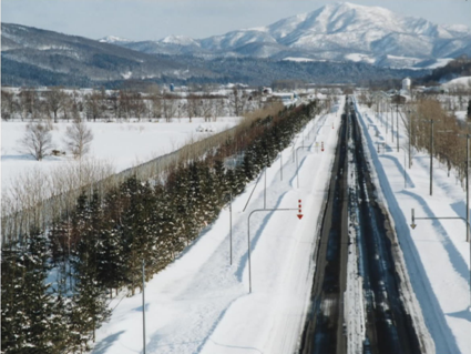
▲Developed snowbreak woods
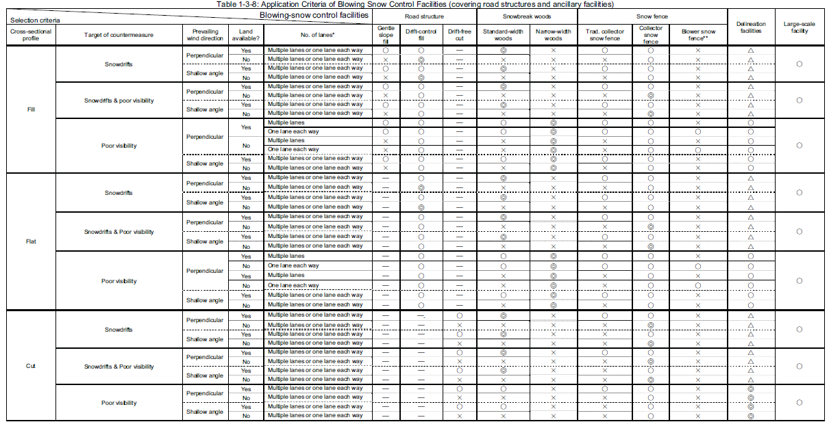
▲Blowing-snow control facility application criteria (Click to enlarge)
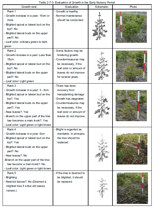
▲Evaluation of growth in the
early nursery period of snowbreak woods
(Click to enlarge)
What is the Highway Snowstorm Countermeasure Manual?
In cold snowy regions, it is vital to ensure winter road safety. In this context, poor visibility and snowdrifts caused by blowing snow are major issues that require effective countermeasures.
The Highway Snowstorm Countermeasure Manual (first edition: 1990; revised edition: 2003) outlines technical standards for the planning, design, construction and maintenance of snowbreak woods, snow fences and other blowing-snow control facilities, and explains the basic principles of the standards.
Measures for blowing-snow control on national highways in Hokkaido are provided in the manual.
March 2011 revision to incorporate new information
The revised manual (2003), which has been downloaded from the CERI website more than 30,000 times, is used as a reference for blowing-snow countermeasures both in mainland Japan and in Hokkaido.
However, since the release of the second edition, blowing-snow control technology has progressed, new information has been acquired and related guidelines have been revised, creating a need to update the manual again.
Against this background, CERI published the third edition in March 2011 to reflect new understanding in the field.
In preparation for the third edition, areas for revision were identified based on questionnaire surveys of people involved in design, construction/maintenance work and technical advice provided by CERI. The Delineation Facilities against Snowstorm Manual (Draft) was integrated into the manual to create a one-stop resource on snowstorm control measures. A committee consisting of experts on blowing-snow control measures was formed to review and revise technical information for the publication.
Major revisions
Blowing-snow control facility application criteria
Replacing the procedure for the selection of a single facility type, the updated criteria enable the selection of multiple facilities from among a wide range of choices.
Simplified method for evaluating the growth of planted trees
Methods for evaluating the growth of planted trees and estimating factors contributing to stunted growth are newly included.
Service roads
To facilitate snowbreak woods maintenance, the inclusion of service roads in such woods was made standard, and the standard drawings of snowbreak woods were changed accordingly.
Available on the Web
The new manual is available on CERI’s website. The Japanese version can be freely downloaded at http://www2.ceri.go.jp/fubuki_manual/.
The English version can be freely downloaded at http://www2.ceri.go.jp/fubuki_manual/index_e.html.
(Contact: Snow and Ice Research Team,CERI)
A study on slope monitoring using Micro Geo-Electric Signals
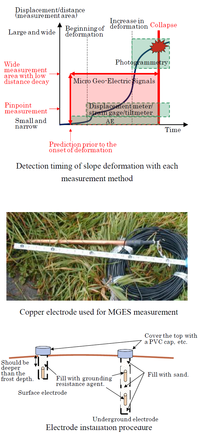
Japan’s geographical and geological conditions make it a country of frequent landslides, rock failures and other geological hazards, which cause damage to elements of social infrastructure such as roads/railways and sometimes the loss of human life. Despite the need for a technology to detect precursors of these events, no such methods have yet been established. Against this background, expectations are high for the development of a technology by which slope collapse can be predicted.
Geologists have long known that electrical potentials are generated before rock and ground failure events occur. As the ground carries a weak electric current, any two points will exhibit a certain difference in electrical potential, generally referred to as earth potential or spontaneous potential. Micro Geo-Electric Signal (MGES) measurement allows the detection of failure precursors from monitoring of spontaneous potential in the ground. This approach is based on the VAN method, which has been used to successfully predict earthquakes in Greece.
Various models have been proposed to represent the mechanism behind the generation of MGES. Based on the test results obtained in this study, the mechanism can be explained with the streaming potential model, in which rock-borne water is considered responsible for the transfer of electrical charges.
MGES measurement is an electromagnetic approach used to determine direct-current (DC) potential difference, which is characterized by low distance decay (i.e., reduction of current with distance). As it enables wide-area measurement and monitoring of ground from the beginning to the end of deformation, hopes are high for its implementation as a new slope failure prediction technique. The measurement procedure involves drilling a hole to a depth of 1 – 2 m in the ground on a slope considered unstable, placing copper electrodes (diameter: 2 cm; length: 50 cm) in the hole at 30 – 50 m intervals, and measuring differences in potential between the electrodes. A data logger or a PC is used to collect the potential measurement
data, which can be automatically transferred and analyzed online.
This research was conducted in conjunction with Fujita Corporation, and the Manual for Slope Monitoring Using Micro Geo-Electric Signals (draft) complied as a result of the project is available on the CERI website at http://chishitsu.ceri.go.jp/soft.html.
(Contact: Geological Hazards Research Team, CERI)